
RECONSTRUCTION SYSTEMS FOR INDUSTRIAL INSPECTION
A. Conci , F. C. Pereira
Pós-Grad. em Comp. Aplicada e Automação - CAA - Pós-Grad. Eng. Mecânica - PGMEC Universidade Federal Fluminense - UFF - CEP 24 210-240 , Niterói , RJ , Brazil
Abstract
One of the principal issues facing researches in industrial vision systems is the 3D reconstruction from parallel planar views. A simple algorithm is presented to solve this problem. It composes vs-octree from region contour(RC) quadtree using manageable span pairs to connect voxels within these pairs. Examples of mechanical shapes to which the algorithm has been successfully applied is presented.
Keywords: Visual inspection, computer vision, reconstruction, quadtree, vs-octree.
1. INTRODUCTION
Many problems in computer vision such as object recognition, measurement, motion estimation and feature prediction benefit from 3D reconstruction. An important class of objects defined by simple engineering drawing cannot be reconstructed by individual sensor, it needs integrating images from distinct sensors. Researches have investigated a variety of sensors and sensor integration techniques for interpretation of multisensory imagery [1]. The fusion of multisensor data can create new features that are less variant to scene conditions, occlusion, and viewing position and thus make possible robust recognition systems, as for example a mobile robot navigation for space applications [2].
Different approaches have been used to design reconstruction systems. From a survey of recent literature, it is found that models for generation of visual images uses generally facet based approaches or constructive solid geometry (CSG) models. The major drawback of the surface facet-based approaches is that they relay on heuristics and large database. They use surface structure representation and do not explicitly model phenomena that giving rise to the different imagery [3].
In this work, the octree representation is used to model the structure of an object. The advantage of these representation are: (1) they speeds up algorithms for Boolean set operations and transformation (viz. union and intersection); (2) geometrical properties as perimeter or surface can easily be computed; (3) tree transversal algorithms (efficiently implemented in parallel) can be used to perform the computation on these structures; (4) there are efficient algorithms for storing octrees; (5) they are property of data compression; (6) it is easy to perform simple transformations ( for example rotation and reflections ) on octrees; (7) topological properties can be obtained efficiently by neighbor finding algorithms in a specified direction [5]; (8) algorithms for displaying octree-encoded objects take advantage of their structures and can be easily implemented [6]. The octree-based reconstruction method is efficient an functional; however, creating an accurate 3D model is problematic when the object is non-convex. The line drawings contain additional detail about the object that can be used in this reconstruction and is not used in the former method. Moreover, the CSG representation is more difficult to construct when compared to the octree from silhouettes approaches.
2. CONSTRUCTION OF OCTREE FROM QUADTREES
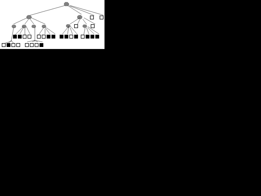
A quadtree is a hierarchical data structure used for efficient representation and encode of 2D binary images. When a quadtree is used to represent an area in the plane, each quadrant may be full, partially full (recursively subdivided into subquadrants), or empty, depending on how much of the quadrant intersects the area. A quadtree is derived by subdividing the 2D plane in both dimensions to form quadrants, until all quadrant are full or empty or a limiting depth is reached. Quadrants are named according to their compass direction relative to the center of their parent: NW, NE, SW and SE ( fig.1).
FIG. 1 - The quadtree representation of a binary image
An octree is an extension of this data structure in 3D. The octree of a object is obtained by subdividing the universe into eight equal octants successively until each octant correspond either to an empty space or to a volume inside the object. Octants are named according to their direction relative to the center of their parent node as: left -L, right-R, up-U, down-D, back-B, and front-F. Each octant is then a node in the tree. Each node either has eight children or is a leaf node. The leaf node can be White ( entirely empty node) or Black ( entirely volume inside object node ). The Gray node is not a leaf node and has eight child nodes that can be Gray, White, or Black. These representation are illustrated in fig 2.
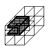
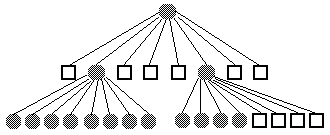
FIG. 2 - The octree representation of a 3D object.
The above octree description is basically a volumetric representation of a 3D object. To relate 2D shaded images with the 3D object efficiently, surface information can be stored in the octree nodes, such octree is named vs-octree [8]. The vs-octree has four types of nodes: internal (Black), empty (White), surface or gray (combination of the others). Multiple silhouettes are used as the input to the vs-octree formation. For each view, the contour of each silhouette is computed and a region contour (RC) quadtree is constructed (Figure 3). Each node, in this representation, can be Black (object), White (non-object), Contour (representing a contour voxel) or Gray (combination of the others). A Gray node is a non-leaf node with children of mixed types (Black, White or Contour). For each surface node, the normal of its surface is computed based on the contour normal in the RC quadtrees. Using a RC quadtree from different views, a volume intersection is performed and the vs-octree constructed
.
3. RECONSTRUCTION SKETCH
In the designed system, object images are supposed taken by tree orthogonal cameras and thresholded into binary silhouette shapes. The system first takes a top view of the object using the top camera (X-axis in fig 3). If the principal axis of the object is not centered on the frame or parallel to the axis of the camera its relative position are normalizes. These normalization can be done by translating the shape centroid to align with the X-axis and rotating the principal axis of the shape to align the Y and Z-axis[10]. This makes the object capture always to be identical in position and orientation (how this can be done are included in the appendix).
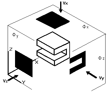
FIG 3. Orthographic views used for reconstruction
Let the silhouettes of the object be obtained by a top-view , Vx, and two side-view images Vy and Vz, along the directions X, Y and Z as shown in fig 3. We assume these axis parallel to the principal axis of each silhouette. Then each silhouette are obtained by orthographically projecting the object onto the three principal orthogonal planes, (F x, F y, F x). Defining a view vector Vi , i Î { x, y, z } , the plane F i onto which the silhouette is projected is spanned by the set of othogonal vectors (u,v) using cross product: -Vi = u x v . The contour of the silhouette in the plane F i is described by
Ci ( t) = < u i (t) , v i (t) > (1)
where t is the position along the contour relative to the starting point. The variable u,v are applicable to each pair of coordinate axis {x,y,z}. Once we fix Vi the contour of each view planes from the other two orthogonal viewpoints are uniquely determined. For example a contour on the plane F x will have the sequence of coordinates value Cx(t)=<y(t),z(t)>. These created contour are the drawing lines (fig. 4). The line drawings are orthographic views which detail not only the silhouette but also the major exterior structures.
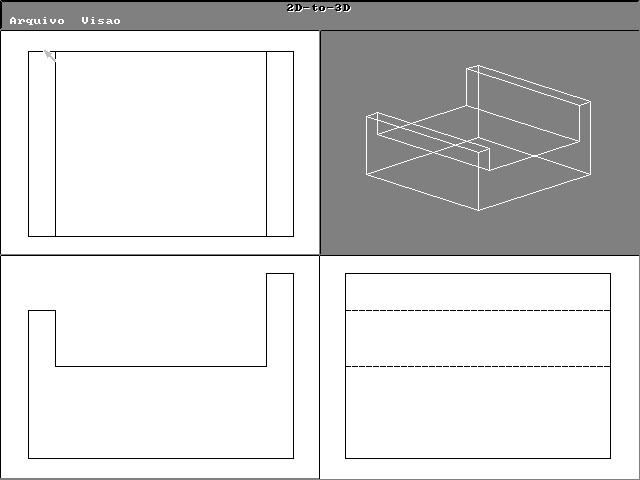
An quadtree is constructed for each separate plane and union operation is performed on the parts to from the octree model. Volume intersection based on the objects’ silhouettes is employed to construct the octree. This procedure detects concavities of the object that will cause occlusion in the model and uses information from the line drawings to model protruding parts. These reconstruction scheme have been used successfully for plane facet objects with concavities (fig 4), or parts (fig. 5) and concavities occluded by another component of the same object (fig. 7). Protruding parts or occlusion can be detected if visible in at least one orthographic plane (fig.6). Concavities can be detected if it has the following pairs of characteristics:(a) some or all of the points on the surface in the concave region must have 3D tangent parallel to the normal of one of the projections planes; and (b) points of the concave region must project to the contour of the silhouette in the detection plane. To reconstruct the visual object from its octree representation, all the surface nodes are checked for visibility[6]. Arbitrary perspective projection can be specified.
4. CONCLUSIONS
A refinement to the octree construction algorithm is presented. Line drawing information is used improving volume intersection technique to eliminate false appearance in the octree from quadtree representation. By revealing the occluded shapes of the object, the accuracy of the volumetric fit of the simulated object to be reconstructed is increased, without the expense of requiring additional cues. This approach is straightforward in its implementation while availing a large number of objects for modeling. The limitation of this approach is its inability to model object surface which do not project to any of the orthographic views. If the 3D points in the concave region do not project to the contour of the silhouette in any of the other projection images, the occlusion will be undetectable.
5. REFERENCES
1.Nandhakumar and J.K. Aggarwal, "Multisensory computer vision", in Advances in Computer, Academic Press, San Diego, 1992.
2.S.Shaw, R. J. P. de Figueiredo, and K. Kumar, "Fusion of radar and optical sensor for space robotic vision", in Proceedings of the IEEE Robotics and Automation Conference, Philadelphia, PA, 1988, pp. 1842-1846.
3.C. H. Chien and J. K. Aggarwal, "Volume/surface octree for the representation of 3-D objects", Computer Vision Graphics Image Process., vol. 36, 1986, pp. 100-113.
4.A. Laurentini, "The visual hull concept for silhouette-based image understanding", IEEE Trans. Pattern Anal. Mach. Intell., vol. 16, n. 2, 1994.
5.H. Samet, "Neighbor Finding in Images Represented by Octrees", Computer Graphics, Vision and Image Processing, vol. 46, n. 3, 1989, pp. 367-386.
6.I. Gargantini, T. Walsh and O. Wu, "Viewing Transformation of Voxel-Based Object in Linear Octrees", IEEE Computer Graphics and Application, vol. 6, n. 10,1986, pp. 12-21.
7.H. H. Chen and T. S. Huang, "A survey of construction and manipulation of octrees", Comput, Vision Graphics and Image Process, vol. 43, n.3, 1988, pp. 409-431.
8.C. H. Chien and J. K. Aggarwal, "Model construction and shape recognition from occluding contours", IEEE Trans. Pattern Analysis and Mach. Intell., vol. 11, n.14, 1988.
9.I. Gargantini, G. Schrack, and H.H. Atkinson, "Adaptive Display of Linear Octrees", Comput. & Graphics, vol. 13, n. 3, 1989, pp. 337-343.
10.C-H. Liu and W-H Tsai, "3D Curved Object Recognition from Multiple 2D Camera Views", in Advances in Computer, Academic Press, 1990, pp. 177-187.
11.A. Goshtasby, "Template Matching in Rotated Images", IEEE Trans. Pattern Analysis and Machine Intelligence, PAMI-7, pp. 338-344, 1985.
ACKNOWLEDGMENTS
The authors wish to thanks the support provided by FAPERJ (E-26/170.94/95) and CNPq ( 302649/87-5 )
APPENDIX
Reconstruction system designed mainly for use in industrial automation presents the parts to be reconstructed placed on the turntable with a robot arm. Object images are taken by cameras and first of all thresholded into a binary silhouette shape for further feature extraction. The object can be in any position on the frame, translating or rotating [11]. At this time the frame can be seem as a square of NxN pixels. Let B denote a set of black pixels, the binary silhouette shape of an object. Each point in B is associated with value 1, others points in the frame is associated with value 0 (zero). The coordinates of the n-th point in B is ( i, j ). The (p,q) order moment of B is defined as
m pq = å n=1N ( i n )p (j n)q (1)
The area of B is m00 and its centroid is (i0,j0), where i0 = m10 / m00 and j0 = m01 / m00 . The ( p, q ) central moment of B is defined as
mpq =å n=1N ( i n - i0 )p (j n - j0-)q (2)
The horizontal and the vertical moment of inertia around the centroid are, respectively m20 and m02.. The principal axis of shape B is defined as the line L about which the moment of inertia of B is minimum. It can be shown that L goes through the centroid of B, and the slope of L, satisfies the equation
tan q = 2 m11 / ( m20 - m02) (3)
The angle of above equation and the coordinates (i0 ,j0 ) of the centroid are used for correctly position the object in relation of the capture camera, or the reconfiguration of the back pixels on the frame.
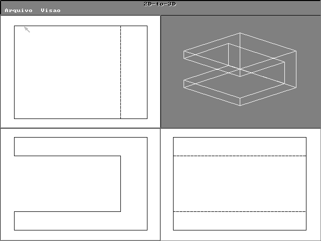
Figure 4.
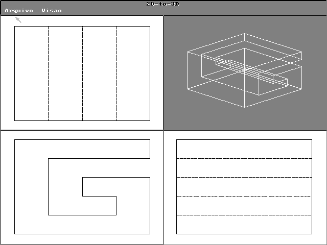
Figure 5
Figure 6.
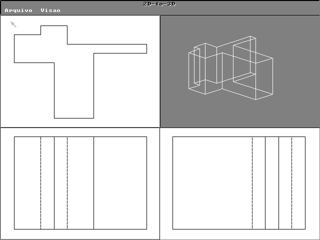
Figure 7